Friday, October 31, 2008

Diagram Diaries


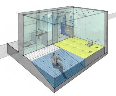
Once again the above image is taken from LTL. Look at how they use the techniques of exploded axon combined with pulling out details at a larger scale. This may be something you can appropriate for your own diagrams. I was generally impressed with the work in this last assignment, and for Tuesday I want to see it all polished up. Do not stop nitpicking your drawings until they are beautiful. Remember that clarity is paramount. Below are some of the best examples from Thursday:

Sunday, October 26, 2008

Ex4-1

Structure Diagramming

exercise goals

To express the structure of a building through clear diagrams. These diagrams should convey the idea of the space without the excessive use of instructional text. Therefore careful attention should be paid to elements such as simple scale figures, arrows, hatching patterns, line thickness, color patches and color choices.

performance procedure

1) Discuss with your instructor the structure of your building. Using you current knowledge of your structure system of choice [tensile, concrete, steel, etc.] develop a system that will work best for your design. Express this structure using an exploded axonometric drawing. This drawing may be simple, but must clearly express your system of choice.

This drawing may be done in a 2d drafting program, but I strongly recommend using a modeling program to manually separate structural layers of your building. Note, the students whose design is situated below grade must show the space from which these building are extruded. This is a very important element of your structural design and must be communicated.

2) With a new found understanding of your structural system of choice, make a new drawing. This drawing will be simple diagram of the loads on your building. Develop this drawing in section and pay careful attention to live and dead loads. The best way to draw these loads is through a hierarchy of arrows. Look at Chin diagrams [or other structure books] to get an example of how these diagrams should look.

For this exercise you will primarily be using Adobe Illustrator. This program is the best for editing graphics, but any ground work for these diagrams may be done by hand, in your drafting program of choice [for example finish sections and plans in autocad, they will be the basis for your diagrams] or your 3d modeler of choice.

BRING ROUGH DRAWINGS AND IDEAS TO CLASS ON THE NEXT CLASS PERIOD, TUESDAY, OCT. 28TH.

3) Use the advice from your crit, and begin to make these diagrams in Illustrator. The program excels at clean and clear graphics, and your diagrams should look the same. Remember that the most important point of these drawings is clear communication.

4) For these diagrams the following requirements should be adhered to:

a) you may only use 2-3 colors (a black, a grey tone and a color of choice)
b) you may only use 2-3 different line weights
c) you must use scale figures, arrows, hatches and/or color patches, but only when appropriate

5) For the final submission you will be required to submit 2 different diagrams, a exploded axonometric of your structure and a 2d section drawing of your structure's loads of your design.

a. A RGB, low res drawing (72 dpi) with a 900 x [choice] image size
required file name: Exxon_XXX_Ex4-1.jpg
b. A RGB, low res drawing (72 dpi) with a 900 x 600 image size
required file name: StrucLoads_XXX_Ex4-1.jpg


The above will be due in your folder on the server and on your blog by the beginning of class on Thursday, October 30th.

Saturday, October 25, 2008

BEST SECTION PHOTO

These two photographs enhance the built model/drawing sections. In Leo's shot, good lighting adds that extra depth to the drawing/model and makes the image come alive. Extra care was taken to line up the shot as directly in-front of the section cut as possible. The darkness of the model and lightness of the paper work well together. Greg H's image has an unusual angle that adds interest to the shot. The viewer needs to study the image to gain an understanding of what is happening. The depth of field is well executed and deepens the shot by having some elements out of focus and other elements crisp and clear. The smudges on the plexi (which don't look good in the physical model) give the photo a texture and point of focus aided by the lighting. Both of these images would look good in a portfolio and demonstrate more than a simple picture taken to prove that the work was completed.


Tuesday, October 21, 2008

Friday, October 17, 2008

Renders for Tuesday

For the next assignment I need you to keep your focus on the design of your water containers. You need to model, in detail, a sample of your pool system. Most of you I have specified exactly what you need to zone in on, but for those still unsure you need to make a section model that demonstrates the unique character of your water container.

    Levels of information include:

  • water drainage and distribution systems

  • structure systems

  • material call outs

  • measurement call outs

and any other additional information that you can think to include in either the modeling, illustrator or photoshop phase of this assignment. Once your model is completed you must take multiple renders [specifically a hidden line and a wireframe] and compile them together in illustrator. This is a step all should be familiar with. After the drawing is compiled you will use the skills you learned in class to add entourage to your drawings. This extra entourage should demonstrate water level, human scale and human interaction with your water contatiner. How this is displayed is individual to the project, so be creative.

DUE: on Tuesday at the beginning of class you will be required to have a final entourage render on your blog. This drawing should be a minimum of 900 pixels [largest dim] at 72 DPI and RGB

LTL Renders:

Wednesday, October 15, 2008

Resources


ILoveSketch from Seok-Hyung Bae on Vimeo.

and check this link out for something invaluable to add to your drawing tool set. This plug-in allows you to bring in .DWG and .DXF files into Illustrator with layers intact. Hopefully this makes your life easier.

Tuesday, October 14, 2008

Ass 2-3 Successes


Clockwise from top left: Hoffman, Marshall, Strickland, Donovan, Spurgin, Redington

I am happy with the results of this project. Huge props to the students that stretched the capabilities of this assignment to their max. Hopefully this has taught you invaluable knowledge on how to successfully use the laser cutter and digital modeling programs as a tool for fabricating structure systems.